
Mentor Calibre DRC/LVS
If you haven't read the CAD tool information page, READ THAT FIRST.
Mentor's Calibre tool has become the
de facto industry standard for layout verification.
NOTE: For Calibre DRC and LVS to properly check your layout, you must have only SHAPE (and not SYM) pins defined in your layout. These must be created using the pin (e.g. M1 pin) metal layers, rather than the drawing (e.g. M1 drw) layers.
DRC
Although designers might be conscious of the design rules when performing the layout, there is a possibility of overlooking and thus violating the design rules. So, DRC (design rule checking) is a step taken to alert us of any violations. This step is important because the violation of any design rules would result in a higher probability, and in some cases an absolute certainty, that the fabricated chip does not work as desired.
To reduce the amount of clutter in your
home directory, first create a directory here called "calibre_DRC_runs". This
is where all the files required and produced by Calibre DRC will be stored.
Select the "Rules" button. If you are seeing 'rules' in the "DRC Rules File" field, you should paste this line in to replace it: /courses/ee4321/tech/tsmc65/T-N65-CM-SP-018-K3_MOM/Base_PDK/PDK_CRN65GP_v1.0c_official_IC61_20101010/Calibre/drc/calibre.drc
In the "Run Directory" field, enter the path to your "calibre_DRC_runs" directory. Double-clicking the folder can help you navigate to this directory.. When you have it selected, hit 'Choose'.
Select the "Inputs" button. Make the sure the "Top Cell" field contains the name of your layout. Also ensure that the file format is GDSII and that the "Export from layout viewer" box is highlighted.Select the 'Outputs' and 'Run Conttrol' buttons. Leave everything by default.
Hit "Run DRC". You can overwrite the files from previous DRC runs when prompted. While DRC is running, you will be shown the transcript file that is being produced.Once DRC has finished running, the RVE
window will be displayed. Read that it displays "Topcell inverter, *
results (in * of * Checks)". This tells you how many errors you received.
A list of all the DRC errors in each cell of your layout will be shown here in a
tree format. Click on the 'Results' title tab to bring up your errors in front
of your checkmarks. You can expand the tree and view each error
separately. Double-clicking on an error number will have Cadence show you
the location of the error in your layout. Also, right-clicking on the
error number will enable you to highlight the error directly on your layout.
Correct the errors and run DRC again to re-check your layout.
You should also see in your CIW window
a line such as "INFO (XSTRM-234): Translation completed. '0' error(s) and '4'
warning(s) found." You can ignore most warnings. Fix all errors until you reach
0 errors.
When you are done, as you close the Calibre DRC window, you may want to save the runset (all your settings so far including the rules file, run directory, etc.) for future repetitions.
The final DRC screen should look like this:

LVS
From the layout window, choose
Calibre -> run nmLVS . If prompted by Load Runset File dialog box, click cancel if this is your first time running LVS. You will then see a series of
buttons to set up the Rules, Inputs, Outputs, and Run Control for Calibre LVS.
Select the "Inputs"
button. Then select the "Layout Path" drop-down. Make sure the "Top Cell" field
contains the name of your layout. Also ensure that the layout file format is
GDSII and that the "Export from layout viewer" box is highlighted. The
other displayed options can be set to their defaults. Then select the "Source Path" dropdown. Ensure
that the "Top Cell" field contains the name of the schematic you wish to
compare. Also make sure that the source file format is SPICE and that the
"Export from schematic viewer" box is highlighted. The other displayed options
can be set to their defaults.
Hit "Run LVS". While LVS is running, you will be shown the transcript file that is being produced. Hit OK for the "Overwrite" windows on the way.
If you get an "error" about net list
generation in your CIW window, go to your schematics window, then, go to
Calibre-> Setup-> Netlist Export. Make sure that your calibre Netlist Export
looks like this:
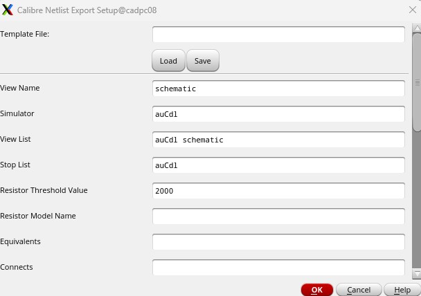
Again, save your runset for further use.
Your final LVS screen should look like this:
